I bought the SSC P7 LED and a heat sink. Since my 4D cells will provide about 6 volts I needed a regulator that could provide a constant current for the LED. I decided to design and build a buck regulator using a ATtiny AVR device. To make sure worked first time I simulated it in LTspice. This is the circuit diagram:

Some parts of the circuit is to simulate the AVR circuit, comparing to the EagleCAD schematic you can see what.


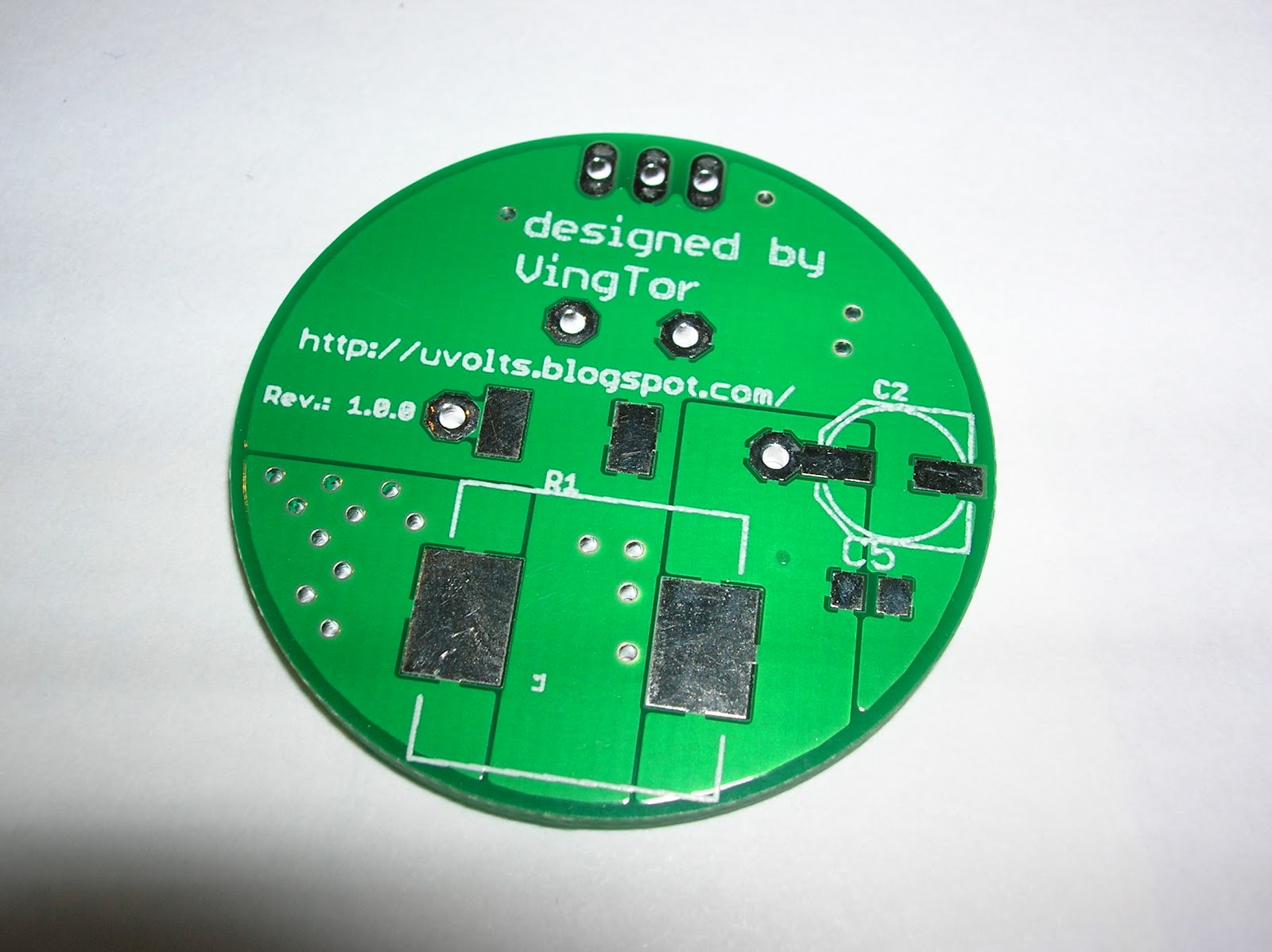
So it was time to solder some parts on to it. Got a bit messy around the AVR, since I had to solder on wires to program the fuses. Also not the the shunt resistor has to be removed when programming with ISP since it is connected to on of the programming lines.


Time to modify the Maglite.There is a little unbrako screw behind the power switch (or inside it if you will), loosen it and the assembly should come out the bottom of the Maglite.

I removed the top part, then soldered on some wires to connect to my PCB.

A picture of the heat sink.

Mounting everything together. The PMOS/NMOS of the driver was glued to the heat sink, so was the LED. I used Arctic Alumina since it is non-conductive, which was a requirement in this case.


Quite happy with the results. My first buck regulator design, so not perfect, I can see several things that I should have done a bit differently now, but it works.
No comments:
Post a Comment